Stoking the steam, one engine at a time…


- © 2018 Steve Allen Contact Me 0
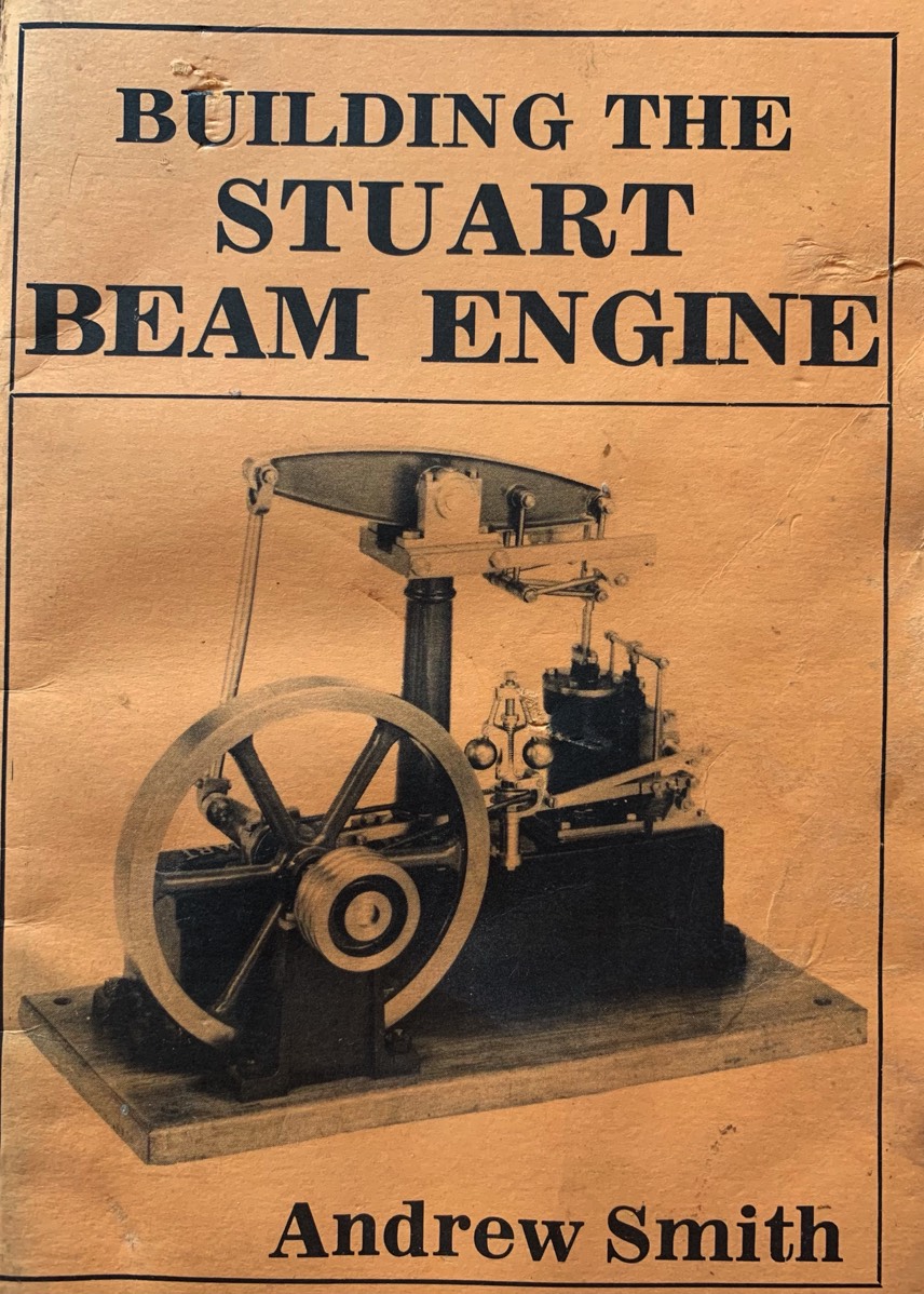
The Stuart Beam Engine
1 in. Bore …2 in. Stroke.
Length … 13 in.
Width … 6 1/2 in.
The beam reaches to a height of 11 1/2 in.
£3 17s. 6d.
Full Set of Castings, Materials, Screws and Drawings.
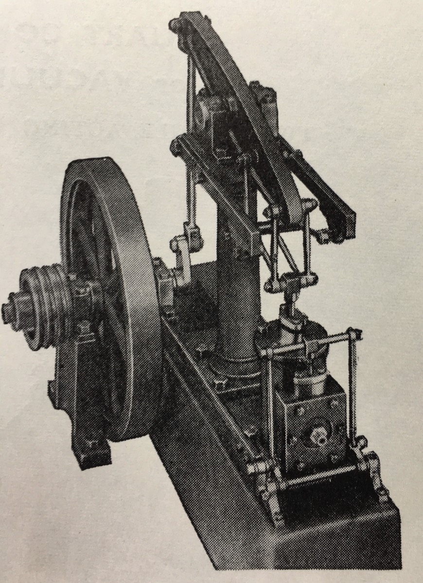
This engine is a Rotative Beam engine using a horizontal bean to convert vertical piston travel to flywheel rotation via a connecting rod and crank. The largest part is the boxbed, a hollow casting with pre-machined surfaces for mounting various parts. A Cast pedestal is provided to mount the bearing for the outer end of the crankshaft, Several of the engines i have seen have a serial number embedded into the top of the casting at the end next to the cylinder mounting. The next largest item is the Pillar, a solid casting with decorative detail cast in. Fitted to the top are two bearings for the beam and arms for the motion gear. The beam sits on a shaft that fits in the bearings, it is secured to the beam by a grubscrew fitted in the beam, a bulge in the casting allows the hole to be drilled without breaking through to the surface of the casting. Often the beam is mounted with this on top ( as seen on the white beam below) but i prefer it to be on the bottom hidden between the bearings. Care must be taken when machining the holes in the beam as accurate geometry is required for smooth running. On each side of the top of the column are the suports for the Watt's parallel motion. This complex arrangements of rods is designed to support the crosshead whilst converting the motion at the end of the beam, which scribes an arc, to the linear vertical movement of the piston rod. The eccentric strap and sheave are mounted inboard on the crankshaft with the rod running horizontally to a neat parallel mechanism that converts the horizontal movement to vertical movement around the sides of the valve chest and via a crossbar down onto the valve rod. The steam inlet is directly fitted to the valve chest cover.
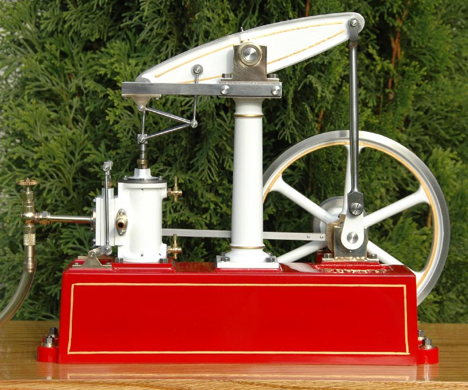
The boxbed is pre-machined but the separate pedestal must be machined to the same height to accurately support the crankshaft. I have found several engines with washers mounted underneath the bearing support to raise the bearing to the correct height. A good sturdy base is required to hold the boxbed and crankshaft support acurately and firmly. Several of the engines i have seen have a serial number embedded into the top of the casting at the end next to the cylinder mounting. Over the years the quality of castings has varied a bit, the column casting on mine had the two halves of the mould misaligned so required an awful lot of filing for a smooth surface. I will someday remove it and turn it down a bit to allow me to flute it lengthways. Beam engine columns were often fluted in the Greek Ionic column style. This complex Watt's parallel arrangement of rods requires accurate machining on numerous identical parts. If the lengths of the rods and mounting hole positions are not accurate the movement may either run stiff or exert a lateral force on the piston rod. Spending a bit of time making a jig would make machining the identical parts accurately a lot easier. Beam engines require a certain amout of mass in their flywheel as they tend to run slower than most engines. The early stuart flywheels were heavy enough for quite a slow speed, later flywheels were lightened by removing metal from the rim between the spokes. This can effect the slow running capability.
The cylinder and valve chest are neatly designed to match the look of original full size engines. They became the building blocks of a range of other engines, Grasshopper, Victoria, Real and James Coombes. Each a different type of engine respectively, Half Beam, Horizontal mill, Upright right way up engine and Table Engine.
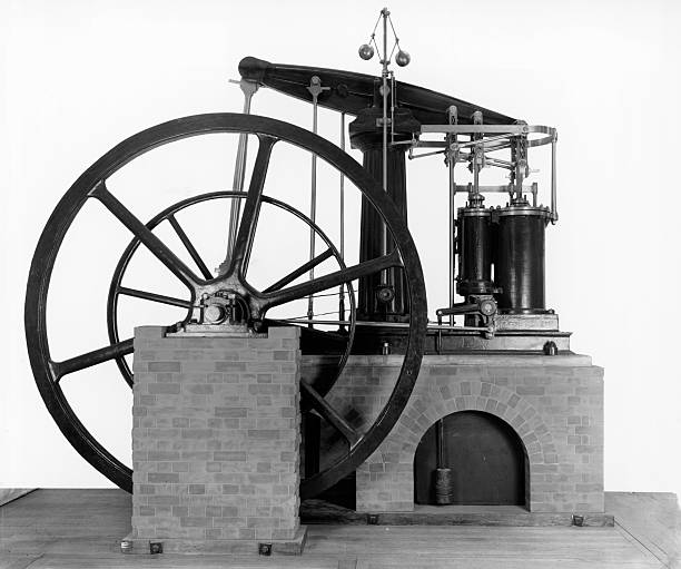
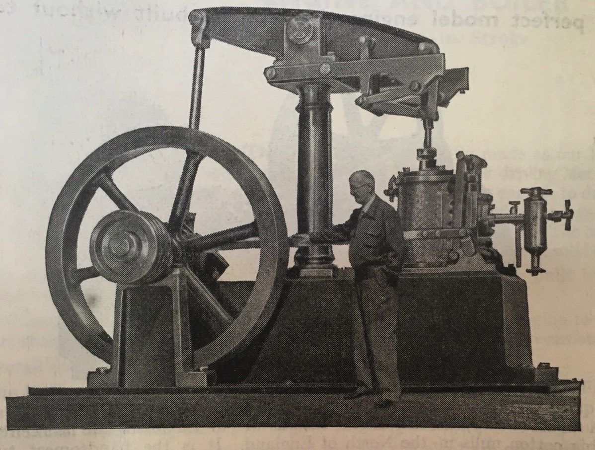
This fullsize engine, mounted for display in a museum features many of the same features as the Stuart model. The main difference to using a large boxbed to provide clearance for the flywheel this engine uses brick platforms for the engine and outer bearing. This particular engine is a twin cylinder compound (as indicated by the different sized cylinders). This allows for much more power and efficiency from the same amount of steam although a high pressure is required. A twin parallel motion is fitted to the beam. A Watt style governor is fitted at the top top provide consistent engine speed. Two water pumps are connected by rods to the left side of the beam.
Beam engine operation is a bit unusual and quite a few people dont understand the intricacies.
When startign beam engines run extremely slow, increasing the speed with each push and pull of the piston. What is happening is that the kinetic energy of the flywheel is being built up to normal running speed. This may take several minutes on a full size engine. When the load is applied it is this kinetic energy in the flywheel that actually does the work, the input from the piston is to top up the kinetic energy. A governor is fitted to allow for variations in the required topup.
With a single cylinder engine the power output from the piston decreases to zero at the ends of travel, the flywheel also smoothes over these variations.
Video Of Stuart Beam Running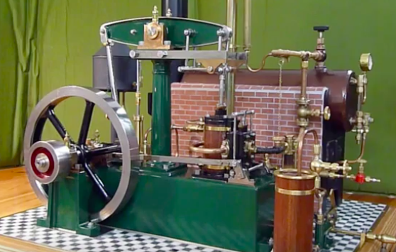
For full details visit Wikipedia's great entry at this link.

Please Consider Making a Donation