Stoking the steam, one engine at a time…

- © 2018 Steve Allen Contact Me 0
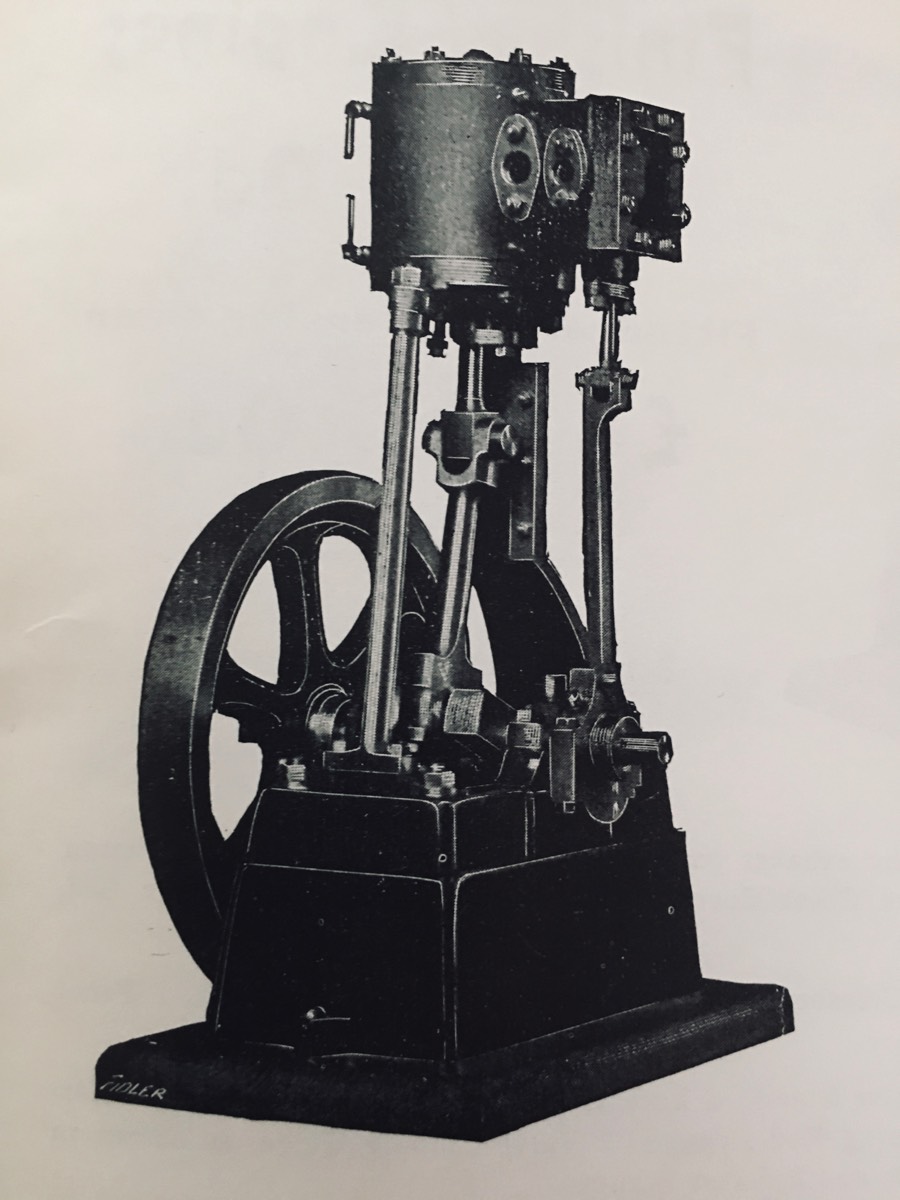
No.1
2 in. Bore, 2 in. Stroke.
Finished Engines
£7 5s. 0d.
Fitted with reversing gear
£8 10s. 0d.
———————————————————
List of Castings and Parts.
CAST IRON. - 1 Cylinder with steam and exhaust ports cast in, 1 Bottom, 1 Cover, 2 Piston Bodies,
1 Valve Chest, 1 Valve Chest Cover, 1 Standard, 1 Bed Plate 1 Boxbed, 1 Eccentric Sheave, 1 Flywheel.
CAST STEEL. - 1 Piston Rod and Crosshead, 1 Crank Shaft, 1 Connecting Rod, 1 Front Column,
1 Eccentric Rod.
GUN-METAL. - 1 Piston Gland, 1 Valve Gland, 2 Eccentric Straps, 2 Main Bearing Brasses,
2 Main Bearing Caps, 2 Connecting Rod Brasses, 1 Valve Spindle Guide, as shown in No2 Picture, 1 Valve Nut, 1 each Steam and Exhaust Flanges.
MILD STEEL. - etc. -2 Crosshead Guide Plates, Cylinder lagging, Valve Rod, Steel for Valve Rod,
Head and Cross Head Bolt, also finished Steel Piston Ring.
DRAWINGS. - A large sheet showing all details full size.
Price, packed in strong box = = = 20/-
EXTRAS
All Studs. Bolts. Nuts. and Screws. over 100. Price 8/-
These are specially made for these Engines, and if used will add considerably to their appearance.
REVERSING GEAR. - Casting in Steel and Gun-Metal, including all Bolts, Nuts and Screws
with full size drawings. Price, 6/6.
Drain Cocks, 3/- per pair. Cylinder Lubricator, 2/-.
––––––––––––––––––––––––––––––––––––––––––––––––––––––––––––––––––––––––
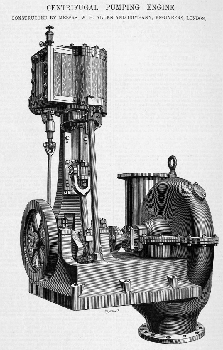
For his first commercial engine Sydney chose a design he was familiar with, one that was used both for marine and land purposes. The engraving below shows a small pumping engine of similar design. Carefully examining the design and it’s evolution it is clear that he considered all the possible elements and selected them to minimise production costs and simplify machining and construction. The engine is of the inverted style with cylinder at the top and crankshaft at the bottom. The cylinder is supported by a cast standard and turned rod. The crosshead runs in a slipper guide machined into the Standard. The cylinder has cast in steam passageways from the valve face to each end of the cylinder and one to the exhaust fitting. Casting these passageways into the casting requires good quality castings but more importantly avoids some complex machining. Around the casting top and bottom lips are 6 bulges in the casting allowing the machinist to choose from 3 different locations, where to fit condensation valves. Having the cylinder symmetrical top and bottom allows the machinist to choose which side the valve chest and exhaust port are on. The piston is machined from two cast iron blanks that are machined the same. The design, having a recess cast into the mating faces allows for what is effectively a hollow piston keeping weight down. The outside diameter of the mating faces is reduced to allow for two piston rings. This is much easier to machine accurately than machining an accurate groove. Thin steel plate is provided to allow fitting of insulation around the cylinder in the recess surrounding the bore. This is normally blued. Brass may also be found for a smarter look and for those perfectionists who really want a miniature replica, wooden boarding can be added with brass straps as can often be seen on the real thing.
Sydney carefully designed for ease of machining.
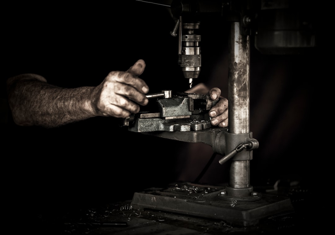
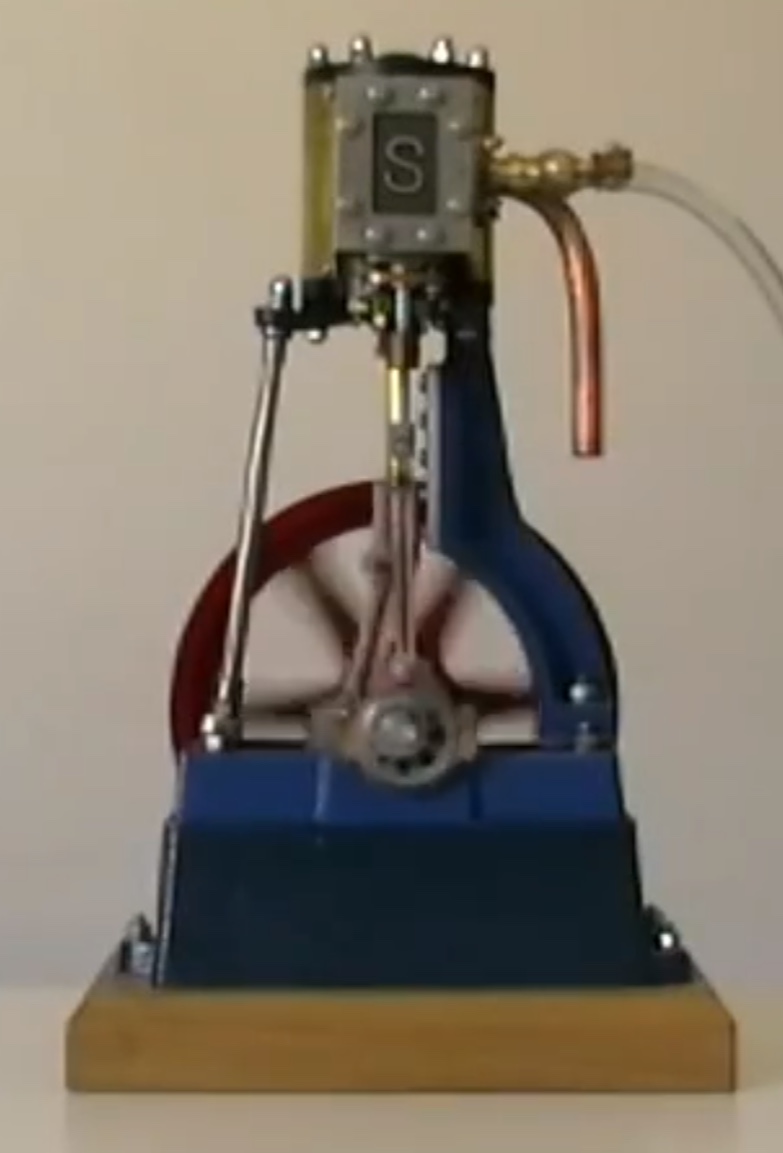
On the top of the cylinder bore fits a domed top cap. Some engines are fitted with a central bolt to allow for effective oiling of the cylinder. For smarter engines a valved oil cup. For the smartest of engines a fat lady may be fitted allowing for oiling whilst the engine is running. The valve chest is fitted to the side of the cylinder on the valve face. On the bottom edge is cast a gland fitting for the valve rod, this is machined out and a brass casting and allows compression of graphite string sealing around the valve rod. Interestingly there is no provision for supporting the valve rod. (See the original advert photo at the start of the chapter.) In the first iteration of the engine it is only supported by the gland packing in the middle. The bottom being connected to the eccentric strap is subject to side forces, the top end is loosely connected to the valve, It is quite possible that these early engines suffered from the valve rubbing against the side of the valve chest or rubbing of the valve rod against the clearance holes in the valve chest and gland fitting. It was obviously a problem because the 1906 brochure mentions the new valve rod support fitted to the bottom of the cylinder, now common on several Stuart designs. Providing support for the valve rod could have been accomplished in several ways and it is worth spending a few minutes discussing this as all the different methods were incorporated into different Stuart designs. Casting a rounded bulge on the top of the valve chest casting allows for a supporting hole to be drilled in conjunction with an extended valve rod, the trouble is that with a casting this size a very long drill is required. (common on most smaller Stuart vertical and horizontal engines.) Alternately you could machine and thread a hole opposite the gland and machine a rounded brass insert to support the valve rod end. This has issues in that this hole must be concentric with the gland hole and must be machined from the other end requiring the valve chest to be mounted twice with a high level of accuracy. A brass or bronze fitting will also need to be machined. This arrangement is used on the Stuart triple expansion engine for the intermediate valve chest that is cast into the main cylinder block. It would be extremely difficult to machine the top of the cylinder block whilst maintaining a cast in support. The last solution is to provide support outside the valve chest on an external bracket. This is the way Stuart went with the No.1 and other large engines. The bronze bracket fits on the underside of the cylinder, it is easy to machine, the important accurate elements are that the hole is perpendicular to the mounting face. Oversize mounting holes allow for easy setup once the valve chest has been fitted to the cylinder. Back to the valve chest, the steam inlet is cast into one side and can be arranged to protrude from the left or right side. It is a lozenge shaped surface that fits a nice bronze fitting. Interestingly early pictures show the engine with the steam inlet and exhaust both on the left or front side of the engine. I can imagine Sydney machining the engine like this for the photos thinking that connecting to a boiler would be easier from the front. Nowadays engineers tend to put the Steam and Exhaust on the right or back of the engine for a cleaner look. The valve chest cover contains an un-machined cast rectangular recess that was originally blank however it currently contains the letter S for Stuart. The valve is free floating on the valve rod to allow steam pressure to seal it against the cylinder valve face. The movement of the valve on the valve rod is restrained by two 90 degree grooves that the rod and a threaded cross piece rest in, valve positioning being adjusted by screwing the cross piece up or down the valve rod. A small steel fitting is machined from square stock to fit the end of the valve rod and connect it to the clevis machined on the end of the cast steel eccentric rod. The rod connects to the eccentric strap. The eccentric strap is constructed of two bronze castings that are machined to fit the eccentric. The eccentric is turned out of steel. The bearing surface for the split strap is machined with a locating ridge that fits into a groove turned into the strap’s bearing surface. The piston rod runs through the stuffing box machined into the lower cylinder cap and uses a similar but larger lozenge shaped compression fitting to the valve rod. The piston rod and crosshead are cast in steel in a one piece design. The crosshead has machined lugs for the slipper guide machined into the cast standard. The two guides are of L cross section. The connecting rod is made from cast steel incorporates the Little end joint at the top and the big end joint at the bottom. The little end is a standard clevis joint with a machined pin usually turned round on one end and a nut on the other. To get the maximum wear the nut side of the clevis is also threaded so that the nut is effectively a locking nut. The pin is now bearing on the crosshead. On some engines I have seen a small anti rotation pin constructed to fit in aligning holes in the round end of the clevis pin and the clevis., both holes in the clevis were clearance holes, the pin preventing rotation and a nut and thinner locknut were fitted. The other end of the connecting rod is machined to a T shape where the big end bearings are bolted. The bearings are split to fit over the crank. I have seen one superior model where the bearings had a steel endplate the the bolts were fitted into sandwiching the bronze between steel. Because of the forces involved the big end usually gets some kind of lubricating feature. Commonly it is a small hole drilled at the neck of the big end behind one of the bolts going down through the steel and bronze bearing to the shaft. The inside of the bearing will often have a small groove cut into the surface in a wiggly pattern to spread the oil across the width of the bearing. The top of the oil hole is often countersunk and painted red in full size practice to indicate an oiling point. On one engine this oil hole was instead connected to a thin copper pipe mounted to the front of the connecting rod up to just below the clevis with a triangular trumpet at the top for easier oiling. The small end often has an oiling hole drilled in it to lubricate the bearing pin. Probably the most ingenious setup was a lubricating point drilled for the small end pin but with a matching drain hole that led to the top of the clevis which had a hole drilled the entire length down the middle to the big end and into the bronze bearing so oiling one point lubricated both bearings.
The crankshaft is made from cast steel. On a couple of engines i have seen fabricated crankshafts. For such a large engine with a lot of mass flying around I am surprised how few engines are fitted with counterweights on the crank webs. This engine running ate rated 1000 RPM and 1/4 HP must be a sight to see, I have only seen them running fairly slowly. The counterweights I have seen fall into the added to cast crankshaft webs or the fabricated crankshaft webs variety. Painted red they are very cool. The flywheel is a standard six spoke affair. But differs from even the 1906 catalogue. The original seems to have a thicker cast rim and the spokes a flat face running out from the hub to the rim. In the later photographs the spokes are oval cross section with webs running between the spokes on the inside of the rim. Pretty much as they do today. With such a large flywheel it is normally keyed to the crankshaft. A solid cast Disk wheel may be fitted instead although this is an indication of a No.2 engine. Some of the Disk wheels have a counterweight cast in to offset the Big end. This is normally mounted facing the engine so is often overlooked. The crankshaft mounts in split bronze bearings with integral bearing strap in the top half. These are mounted into machined slots in the soleplate. The column and rod are mounted to raised and machined surfaces on the soleplate. The whole engine is then mounted to a Boxbed to give clearance for the large Flywheel. Extras The cylinder drain valves were available to be fitted to both ends to enable condensate to be purged. Reversing Gear For those who want to deck this engine out, a set of castings for Stephenson reversing gear are available. (Designed by two employees in Stephenson’s Locomotive Works, William Howe & William Williams, in 1841) The control lever pivots on a bracket mounted to the right side of the steam chest. A knurled wheel on the arm locks the position of the lever acting on a slotted bracket fitted to the front left of the steam chest cover. The lever operates a quadrant, launch type, which positions one of the two eccentrics below the valve rod, which is connected to a sliding block running in a curved slot in the quadrant. The two eccentric straps are of the same design as the standard engine’s although shorter. The two eccentrics are machined from a single casting giving a fixed angle between them. Some engines may have individual eccentrics fixed to the crankshaft separately or pinned together. In practice setting up the eccentric timing with a single casting double eccentrics can be quite difficult as the fixed angle between the two means that you can’t optimize the timing for both directions. Given that the forces at work in both directions are not exactly the same. This often results in the engine running slightly better in one direction that the other. Having two separate eccentrics allow you to optimize the timing on both directions. One advantage of the Stephenson link is that you can continuously vary the valve throw thus for each stroke you can control the amount of steam entering the cylinder. This allows you to ease back on steam consumption when up to speed, this is known as “Linking Up” or “Notching Up”. This late steam entry and early cutoff works well with steam but not as well with compressed air.
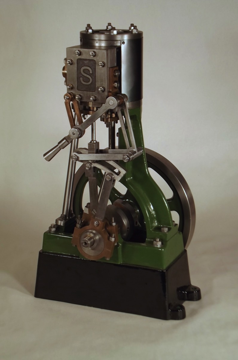
For his first commercial engine Sydney chose a very clever design, reducing production costs and allowing for simpler machining and construction. The cast Standard & Rod design reduces the size of castings required compared with other designs such as the double standard or A frame trunk designs. A single Standard is quicker to machine and will easily fit on a small lathe. Double Standards designs obviously take twice as long to machine and A Frames require a larger lathe. The single Standard also requires less accurate machining than the Double Standard and is also easier to align the piston, crosshead and crank. The support Rod can be machined to fit the assembled engine. The earliest images of this engine show no support for the valve rod, relying on the valve and stuffing box to ensure smooth movement. It appears as though this was not satisfactory as very shortly an external guide was added to the design. This is an easily machined bracket. A common alternative guide is in the form of a rounded bulge on the top of the valve chest that is internally drilled to support the valve rod end. This requires a long drill to drill the guide hole. It also requires careful machining on the outside to look smart. Another alternative is machining a separate rounded support that is fitted to the top of the valve chest. This requires an extra part to be machined as well as the valve chest to be accurately machined from both ends.
The No.1, a classic for all time.
One down side to this engine layout is that it is designed to run in one direction. This is with the connecting rod pushing away from the standard on the downstroke. This is due to the crosshead guide only providing support on one side, the machined Standard side. With the crankshaft running in the correct direction the crosshead is pushed into the standard bearing surface and pulled into it on the up stroke. Running the engine in reverse apples force to the crosshead guides that are not designed for full support. This limitation is I believe why Stuart introduced the double standard designed No.5 a few years later with options for a slip eccentric or Stephenson's reversing gear. to change the engines direction. (slip eccentrics are simpler to manufacture but require the engine to be stopped to reposition the eccentric strap) Over the years the No.1 has not changed apart from the valve rod guide and the steam chest cover Logo. This makes dating the engines very difficult. Instead of evolving the engine to improve its capabilities Sydney introduced new engines with better capabilities in different areas so that customers could choose to best match their requirements, hence the No.2 faster, No.5 improved bi-directional running, No.5a improved BHP, etc... This makes the No.1 a classic for all time.

Please Consider Making a Donation