Stoking the steam, one engine at a time…

- © 2018 Steve Allen Contact Me 0
REAL
1 in. Bore 2 in. Stroke.
Original Style
Vertical Engine
price:
£195
Full Set of Castings, Materials, Screws and Drawings.
Contents
Cast Iron: Baseplate, entablature, pulley, crank, cylinder, valve chest and cover, top and bottom cylinder covers, piston, 7 in. flywheel.
Brass: Slide valve, eccentric strap, valve operating block, glands, conrod bush, crankshaft bearings.
Steel: Crankshaft, connecting rod, eccentric sheave, eccentric rod, clevis, brace, crankpin, piston and valve rods, all materials for valve gear.
Sundries: Detailed drawings, gaskets, "O" ring, gland packing, fixings pack.
Extras
Oil cups, drain cocks, Medium steam and exhaust pipe set, tee piece, displacement lubricator, paint set, alternate piston rings.
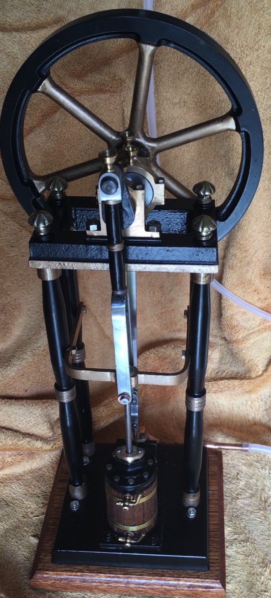
This unusual engine, was designed in the 1970's by Andrew Wood. The engine is based on the cylinder and valve gear common to the Beam, Victoria, Grasshopper and James Coombes engines. Often described as an upside down engine, this is inaccurate. Early steam engines were normally designed with the heavy part, the cylinder, on the ground with the lighter parts up in the air. This allows for a smaller footprint than horizontal engines. Thus engines with the cylinder at the top are correctly called 'inverted' engines and this is a 'real' engine. This engine is supported on four columns, early engines often relied on building walls as part of the engine structure, as seen below. The cylinder is mounted directly to the baseplate with the valve chest to the rear. Four columns mount the soleplate at the top. Two bronze bearings mount the crankshaft with the crank fitted to the front with the flywheel to the rear. Early engines had a small pulley mounted within the soleplate which made fitting a drive band difficult. It is obvious from running the engine at any speed that the unbalanced crank causes excessive vibrations being mounted so high above the small base. At some point this problem was recognised and the pulley was replaced with a counterweighted cast pulley for mounting in the same way. How effective this was is unknown as they did away with this and instead supplied the standard pulley mounted behind the flywheel on an extended crankshaft. The valve rod is connected to eccentric strap by a long bar via a clevis. The same as the Victoria. The piston rod is double the normal length and is supported at the top by a brass bearing mounted on the band fitted halfway up the columns. Halfway up the piston rod is a small pivot block that fits into the connecting rod. This is the weakest point on the engine. the block is fitted using a split pin running through the small diameter piston rod. A better fixing method in my opinion would be to machine two flats on the piston rod and extend the bearing bolts to engage in these. The length of the bolts would have to be modified to accurately allow fixing to the piston rod and still allow clearance for the connecting rod. The connecting rod is itself an unusual design, often called a 'tuning fork'. This is the most difficult part to construct and i have seen several different construction methods. Machined from a single piece of steel, the forks and single part machined separtely and screwed, welded together. three pieces fitted together tuning fork end bent from bar and fitted to single piece. The other big problem is aligning the cylinder, piston rod, piston rod bearing, connecting rod and crank.
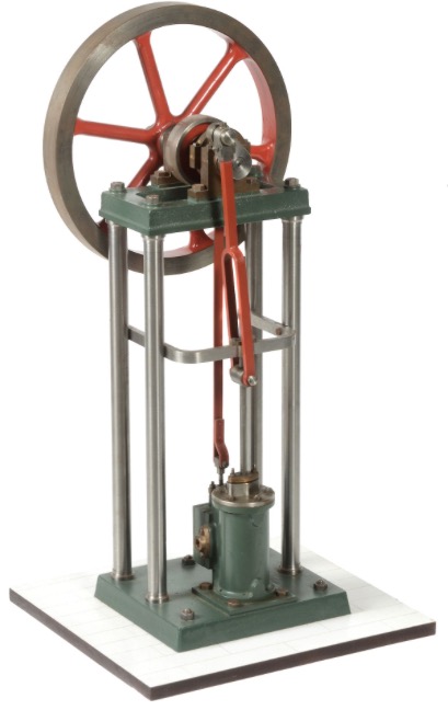
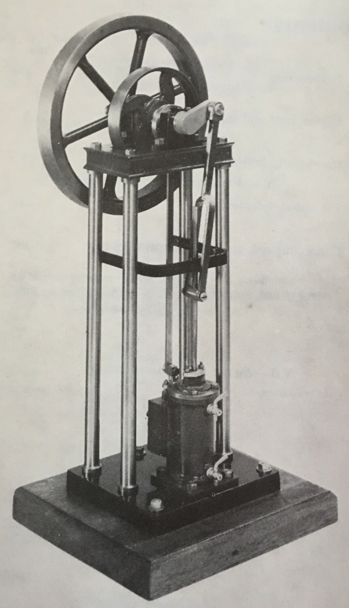
This early engine feature the small counterbalanced pulley mounted within the soleplate at the top of the engine. The flywheel is of the early type that has a solid outer rim. The later version has cutouts between the spokes. The connecting rod appears to be of 2 piece construction with bent fork end. No drain valves have been fitted although the bulges on the front of the cylinder casting are crearly visible. A vertical mounted cylinder like this doesnt really require the valves that allow condensate to be vented from the cylinder whilst it is warming up. Condensate is easily passed out through the valve chest. Horisontal engines with the valve chest mounted on the top really do require them as condensate really doesnt clear well.
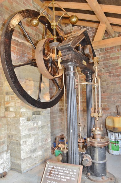
This early engine uses an extension to the wall to mount one of the crankshaft bearings. Also of note is the flywheel which was made from wrought ireon spoke cast into the hub and rim. The decorative columns and pintle are typical of early engines where the look was deemed important. Also fitted is a small boiler feed pump behind the valve chest.The two balls are a Watt's governor, they maintain engine speed despite varying loads and steam pressures.
video of Stuart Real running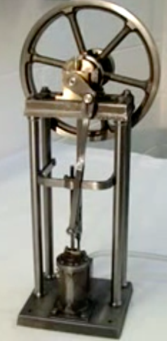
Governor Designs
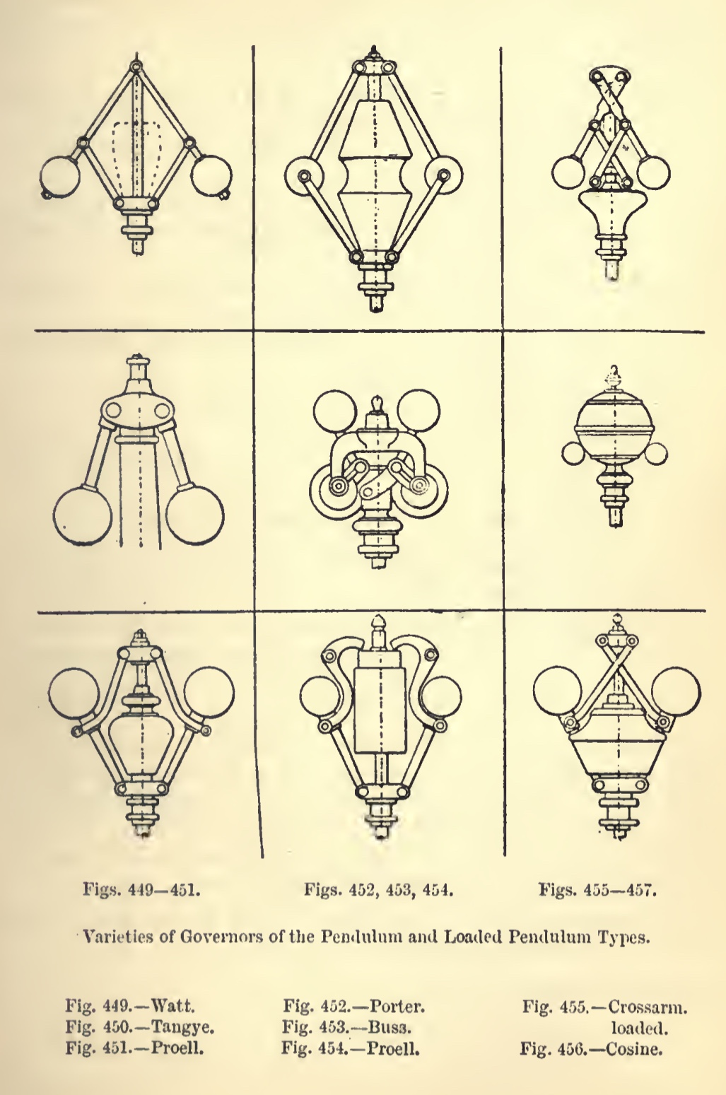
Governors are used to control the engine speed despite varying workloads and steam pressures. Some are designed for low speeds and others for high speeds. Some have a dash pot fitted, an oil filled damper to smooth out changes.

Please Consider Making a Donation