Stoking the steam, one engine at a time…

- © 2018 Steve Allen Contact Me 0
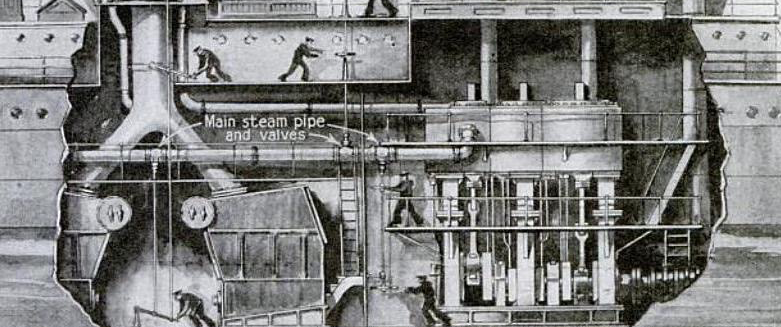
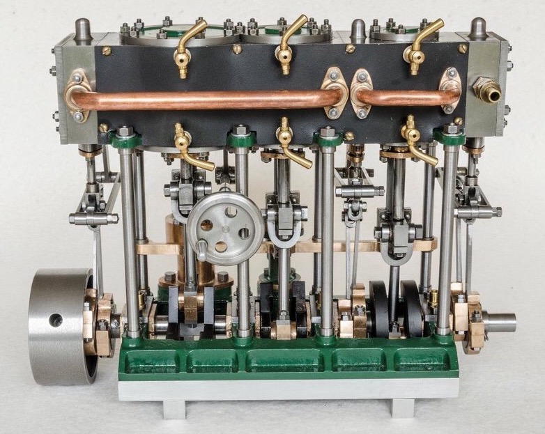
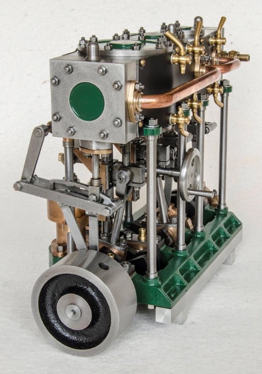
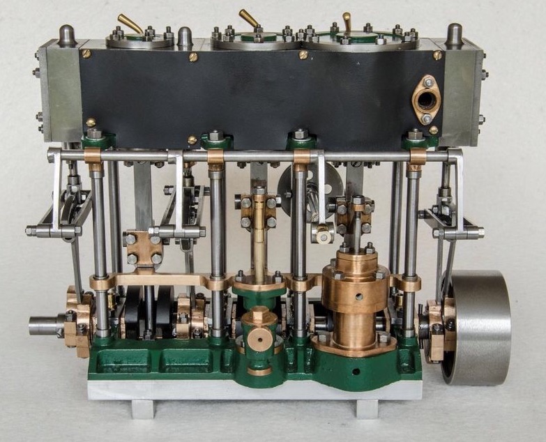
TRIPLE EXPANSION ENGINE.
3/4-in., 1 1/4-in. and 1 3/4-in x 1-in. Stroke. (weight, 17 lbs.)
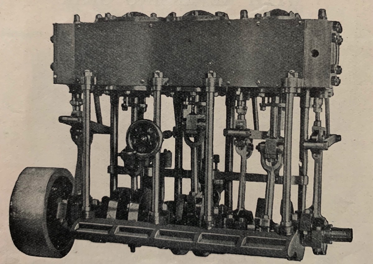
A beautiful example of a marine engine and a most successful working model.
LIST OF CASTINGS AND PARTS
CAST IRON.- 1 H.P. Cylinder, 2 Covers, 1 Piston, 1 each Valve Chest and Cover, 1 combined I.P. and L.P.-Cylinders, 4 Covers, 2 Pistons, 1 each L.P. Valve Chest and Cover, 1 Bed Plate, 6 Eccentric Sheaves, 1 Disc Wheel, 6 Counterbalance Weights.
GUNMETAL.- 3 Piston Rod Glands, 3 Valve Rod Glands, 1 Bracket for lower end of Guide Bars, 4 Pairs main Bearing Brasses, 3 pairs Con-rid Big End Brasses, 6 Eccentric Strap, 3 Slide Valves, 1 Feed Pump Body, 1 Feed Pump Gland, 1 Valve Box and Cover, 1 Crosshead Slide Plate, 2 Crosshead Slide Plates with Brackets for Feed and Air Pump, 4 Receiver Pipe Flanges, 3 Air Pump Castings, 1 Hand Wheel, 4 Brackets, 1 Stuffing Box for H.P. Valve.
STEEL.- 1 Crankshaft, 3 Connecting Rods, 3 Piston Rods.
SUNDRIES.- All materials in steel and brass with all necessary Studs, Nuts, Bolts and Screws, Lagging etc… with two sheets of fully detailed working Drawings.
Price. £4 (Weight, packed 22 lbs.)
EXTRAS.
Set of 6 Drain Cocks, 12/- ; 3 Cylinder Lubricators, 6/9.
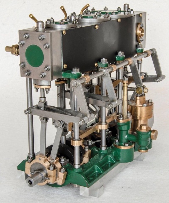
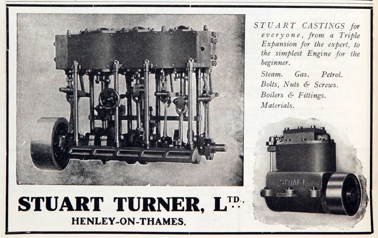
The Soleplate mounts 4 bearing brasses. It is setup for two sets of eccentrics to be outside the soleplate but on set, for the I.P. cylinder to be inside, next to the H.P. Crank. 8 mounting rods are used to support the large cylinder blocks. The back of the soleplate has cast bases for the water feed pump, running off the I.P. crosshead and a condenser air pump running off the L.P. crosshead. the crankshaft has the cranks equally spaced 120 degrees apart, clockwise looking from the H.P. end. Counterweights are fixed to the crank webs. Standard Stephenson reversing gear is fitted for each cylinder, the only unusual feature being te the eccentric sheaves for the I.P. cylinder are split as they with between two sets of crank webs. Standard big end split brasses are fitted. The crosshead guides are flat plates fixed at the top to the cylinder block and at the bottom to a bronze bracket that is fixed to the back four support rods. Two of the crossheads have an extra bracket on the back to operate; L.P. a condenser air pump, I.P. a boiler feed water pump. The two cylinder blocks have tabs for the mounting rods. The H.P. cylinder block has a valve face for a slide valve chest and cover. the other side has extensions that are effectively the slide valve chest and cover for the I.P. cylinder, mounting the valve gland and valve rod extension. (this is a machined and screwed in extra.) The main cylinder block consistes of the I.P. cylinder and valve face which is mounted to the H.P. cylinder block. Having the I.P. valve chest part of the H.P. cylinder block makes machining the two casting easier but it means that when assembling the engine the I.P. reversing gear and valve rod have to be fitted with the cylinder blocks attached. Also adjusting the I.P. valce has to be performed blind. One method of installing is to mount the H.P. cylinder block by itself and fit the I.P. reversing and valve gear, then offer up the main cylinder block and set the valve position before mounting the main cylinder block and bolting the two together. The L.P. cylinder has a standard valve chest. Piping for the steam inlet and exhaust is effectively a daisy chain due to the expansion nature of the engine. HP exhaust to I.P inlet, I.P. exhaust to L.P. inlet. care must be taken when machining the inlet and exhaust ports so that they connections are on the correct side. The image in the catalog indicates that the piping is on the back side of the engine, however the images below show it on the front. Provision in the casting allows either to be machined. So your choice is clean looks or plenty of brass. The Connecting pipe between the H.P. exhaust and the I.P. inlet should be lagged to reduce steam condensate due to the chilling effect of the pressure reduction. On some large expansion engines I have noticed that this connecting pipe is lagged with a steam jacket to keep it hot. Because the engine is an expansion type there is no self starting. On full size marine engines this is not acceptable where switching directions needs to be performed at speed. So a special simpling valve is used that rearranges steam flow to connect high pressure steam to the I.P. cylinder kicking over the engine. The simpling valve is very complex so model makers use a much simpler valving system. The install an impulse valve. This on off valve is connected to the H.P. valve chest and the I.P. valve chest. if the engine stops with the H.P. at either T.D.C. or B.D.C. ,(non starting) a quick pulse from the impulse valve will inject High pressure steam directly into the I.P. valve chest. Because the I.P. crank is 120 degrees off from the H.P. crank it must be in a starting position. The high pressure steam on both sides of the H.P. cylinder renders it inactive and the I.P. cylinder now charged with high pressure steam turns over the engine. Closing the impulse valve with the engine turning returns it to expansion operation. I have seen a modified steam whistle type valve used as an impulse valve for radio controlled operation. This engine is the most complex and dificult to machine, many machinists give up part way through construction so part completed models are often found for sale.
Video Of Triple
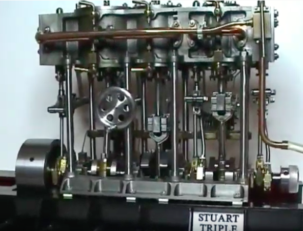
Another Triple running on steam and fitted with thrust block and Propellor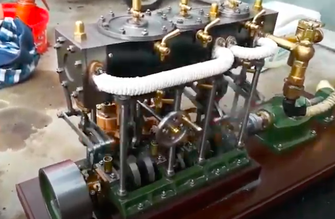

Please Consider Making a Donation