Stoking the steam, one engine at a time…

- © 2018 Steve Allen Contact Me 0
HIGH SPEED
ENCLOSED SINGLE ACTING ENGINES
WITH BALANCED PISTONS.
Suitable for Fast Model Torpedo Boat Destroyers
and Racing Craft.
That the Single-Acting Steam Engine has many points of superiority where extremely high speeds are required, is well-known. This fact, coupled with the desire to provide a suitable engine for speed boats which should be light (for the power developed), have a small number of working parts, be compact, and take up very little head room, has led us to design and produce the engines illustrated herewith.
All the engines have twin cylinders with a single steam chest containing one Slide Valve, They have two cylinders placed longitudinally. This provides a perfectly balanced engine for a single screw or, in the case of a large twin screw model, one engine on each screw shaft may be used.
ENGINE No. 1
3/4 x 3/4 double cylinder, for 4-ft. 6-in. Boat, or two for 5-ft.6-in. Twin Screw Boat.
Finished Engine Complete and ready for steam. Weight 2-lbs. Height 3 1,2-ins. £1 7 6
Castings and Materials
Iron Castings.— for Cylinders and Crank Chamber (2 castings), 2 Pistons, 1 each Valve Chest and Door, Flywheel, Cam-plate.
Gunmetal Castings.— for Connecting Rods, Slide Valve, Gland and Lever Bracket.
Sundries.—- 1 Crank Shaft, materials for Valve Rod, Lever, Lagging, Cam, Ball, Spring and all Screws, with Complete Drawing.
(Weight packed 3 lbs.) Post. 5d. extra … Price, 6/-
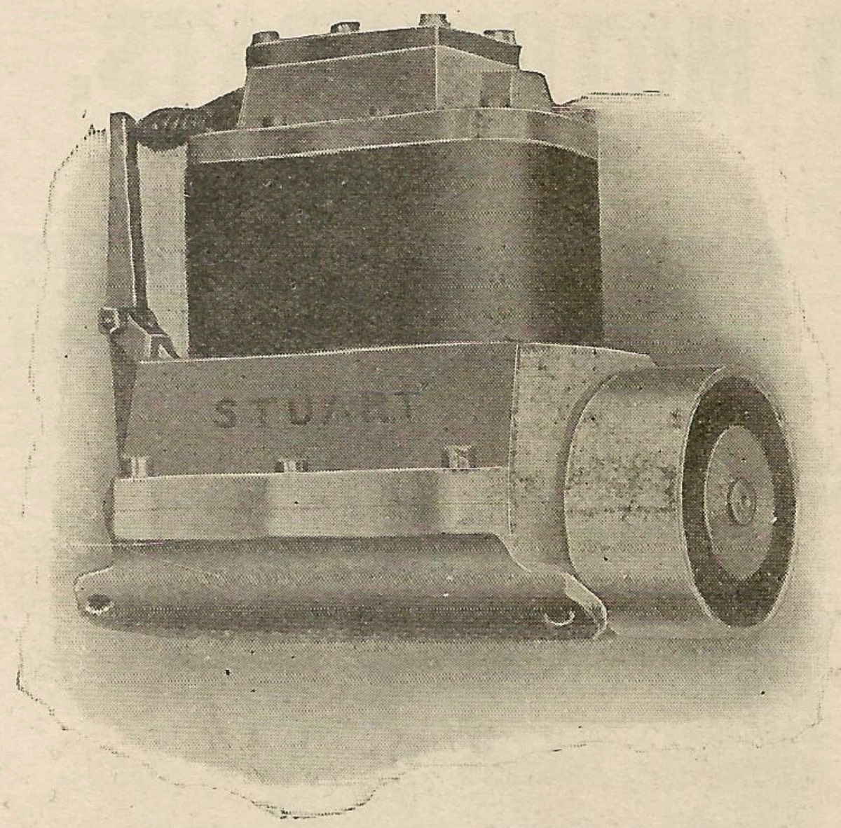
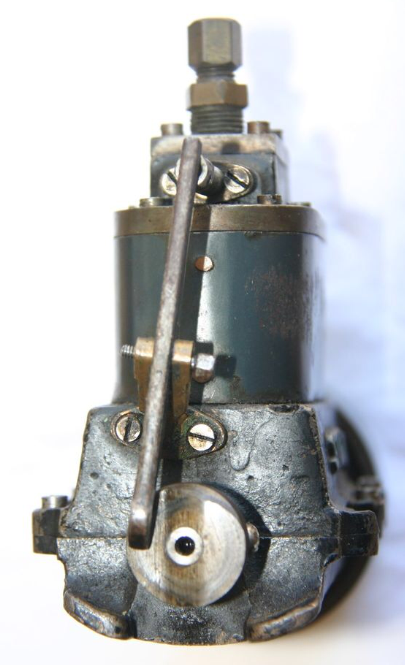
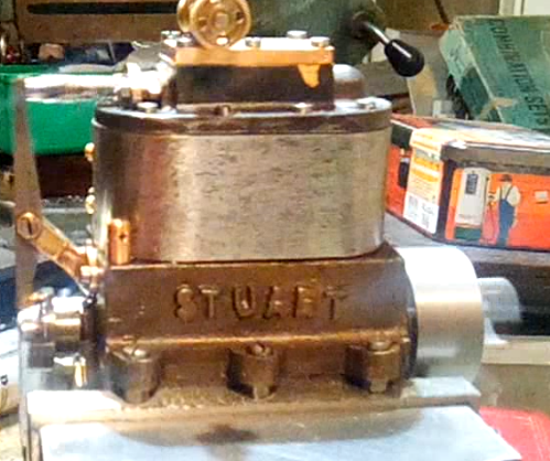
The M.T.B. 1 engine was only appears in the 1924 catalogue so was available for a much shorter time than the other versions. Considering the similarities between all the M.T.B. engines it may be the main diference that is the reason. This first engine uses a very interesting valve control mechanism. On the end of the crankshaft is a brass with a cam cut into the end. Rubbing against this is a Stainless steel ball bearing held in place by a cup machined into the end of the lever arm. This ball bearing provides a very smooth bearing surface against the cam which pushes on the lever arm as the crankshaft rotates. The pivot bracket is mounted at an angle to position the ball correctly. The top end of the lever arm presses against the sprung loaded adjustable end of the valve rod. This is similar to the way an ICE engine tapped rod is setup. The spring is important to provide valve return and tension the ball bearing. The lever is angled so that the friction on the cam doesn't push sideways on the lever. The first picture below shows this setup. The second and third images show a variation where the ball bearing has been replaced by a curved end of the lever, this will obviously increase wear. This lever setup only appears on this engine and in my opinion is problematic, should anything bump the top of the lever arm the ball bearing would disappear if it is not fixed in place. Noting the short availability of this engine and by comparing it with the M.T.B. 1b it could be concluded that the 1b is the replacement for this engine, updated and improved. The hole in the side of the Blue'd steel lagging is the steam exhaust. The valve chest cover is fitted with a steam inlet and a decorative oiler that allows oil to be added whilst the engine is running.
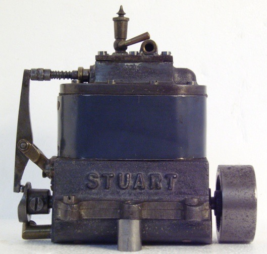
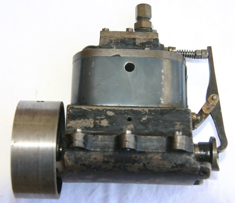
Stuart M.T.B. 1

Please Consider Making a Donation