Stoking the steam, one engine at a time…


- © 2018 Steve Allen Contact Me 0
STUART NO.9
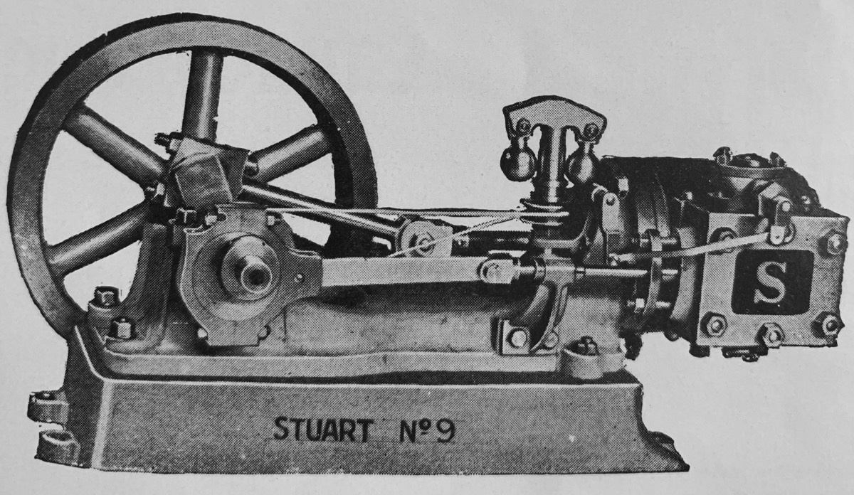
1½ in. Bore, 1½ in. Stroke
List of Castings and Parts.
CAST IRON.- Cylinder with Steam Ports cast in ; 2 Covers, 1 Piston, 1 Valve Chest, 1 Cover, 1 Bed Plate, 1 Box Bed, 1 Eccentric Sheave, 1 Flywheel.
GUN-METAL.- 1 Piston Gland, 1 Valve Gland, 1 Valve Rod Guide, 4 Main Bearing Brasses, 2 Connecting Rod Brasses, 1 Steam Flange, 1 Valve Nut ; 1 Exhaust Flange ; 1 Pair Eccentric Straps.
CAST STEEL.- ! Crank Shaft, 1 Connecting Rod, 1 Crosshead (cored out).
MILD STEEL.-2 Guide Plates, 1 Piston Rod, 1 Valve Rod, 1 Eccentric Rod, 1 Piece Steel for lagging, 1 Hard Brass Valve Rod Head.
Full-size Working Drawing showing every detail.
Price, packed, 13/-
Finished Engines = = = £5 10s. 0d.
Govenors = 27/6. Pump = 15/-
EXTRAS.
All Studs, Bolts and Screws for Engine only, 5/6. Ditto for Governors, 1/- Ditto for Pump, 1/- Finished Valve Boxes, see page 7. Castings for Pump, 5/- Ditto for Governors, 5/-, including Drawings and Sundries. Cylinder Drain Cocks, 2/9 per pair. Lubricators, 1/9.
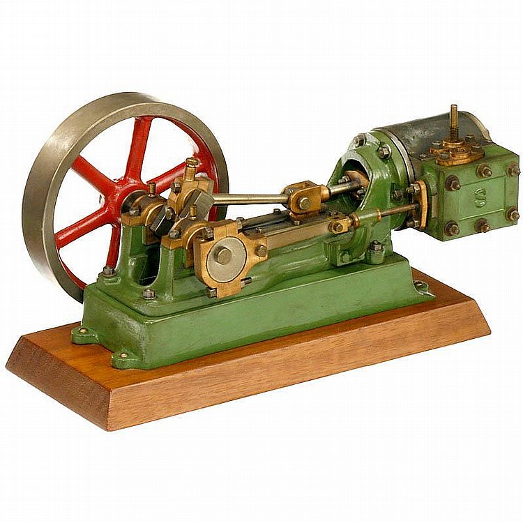
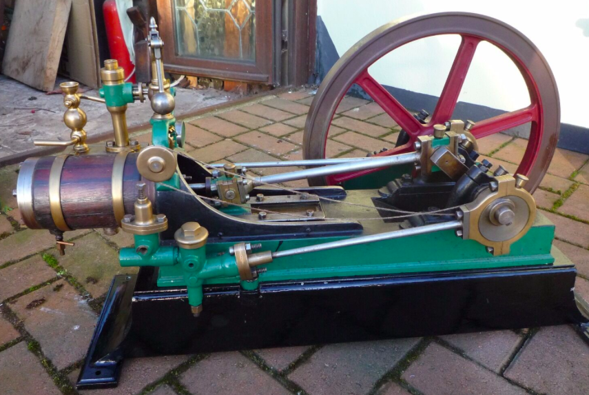
As with the No.8, the No4. has been modified to work horizontally, using many of the same parts. (my No.9 cylinder block is marked 4) Those used from the No.4 are; Cylinder,Crankshaft, Eccentrics, Con Rod, Crosshead, Cylinder Block, Valve Chest. Only the Base, Soleplate and Valve Rod Guide are modified. The valve rod guide comes in two designs , one with the standard engine and another with a flat top for mounting of the Governor on top. (Occasionally you will find an engine with the flat top version but without the Governor, this I believe is because the engine was purchased with this accessory only to discover that machining the parts requires very accurate machining and a lot of fettling to get it to work. And this was discarded.) As mentioned in the No.8 description the Cylinder mounting ring does not allow even spacing of the mounting bolts due to the design. As this is a large bore cylinder, this could cause problems with steam seepage and having to tighten bold higher than is acceptable. The design has been set so that a blond bolt is fitted underneath to spread the load. It is quite awkward to machine and fit this so often it is omitted. This is a good indication of the will and skill of the original machinist. Interestingly this is the first engine illustrated in a Stuart catalogue that is fitted with a Valve Chest Cover emblazoned with the now Classic "S". Despite this i have come across several that have a blank cover. (Whoops forgot to mention this as a casting different fro the No.4. Maybe this is why some come with blank covers.) One design point worthy of note is the lubricator for the Connecting rod big end bearing. The design of the lower bearing brass has an extension to the block in the form of an oil cup, feedign oil directly to the crankshaft. A small screw cap is machined to fit on the top to prevent splashing when running at speed. This is quite tricky to machine so is not found on all engines and the top cap is often missing. This oil reservoir allows running the engine for longer periods without stopping for oiling. Unlike the No.4 whis hasnt any room to fit a cup like this, smart machinists drill a small oiling hole next to the brass mounting bolt to allow oil to get to the middle of the brasses.
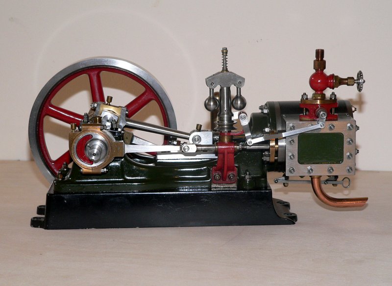
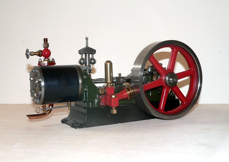
The extras available for this engine are probably the most useful available to any Stuart engine. The governor is a real working design. It is connected by a spring or leather belt to a pulley fitted between the eccentric sheave and the Crank Shaft Brass. It is often Screwed to the back of the Sheave to prevent slipping. This is due to it having to be very thin to allow the eccentric to line up with the Valve Chest correctly.Mounted to the top of the Valve Rod Guide is a small bracket that mounts the pivot for the connecting rod to the Steam Valve. On top of this is mounted the Governor itself. It is a swing ball design which, is raised and lowered by the centripetal force acting on the balls against a spin mounted above the main body. (The spring is not shown in the catalogue image whichh appears to have been Photoshopped out.) The up / down movement is converted to a lateral movement and passed on to the valve mounted to the top of the Valve Chest. This is a very small butterfly valve that also requires a high degree of accuracy and fettling to get working properly. Because of the very small dimensions it is not very effective at cutting down the steam pressure and to get this to actually regulate the engine speed the governor must be carefully adjusted by the spring tensioner so that at the operating pressure used the valve operates near fully closed position. Correctly adjusted the governor will maintain the engine running speed, but only with a mall rage of variables. Regardless the operation and moving parts make this a delightful accessory. You will occasionally find a No.9 with the later governor design, created for the Beam engine and related models. That one is much easier to machine and construct, but doesn't have the chunky industrial design of the original.
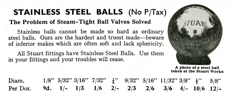
The other accessory is the Boiler Feed Pump. Fitted to the back of the engine, The eccentric is mounted between the Flywheel and the Crankshaft Brasses. This is occasionally found with a slim design and keyed to the Crankshaft along with the Flywheel. The pump design is very simple to construct consisting of a main pump body angled to align with the eccentric. To it are bolted small cubic blocks each containing a ball valve, one mounted to the side contains the pump input valve, the one mounted to the top contains the pump output ball valve with a small bolt on top to allow fitting the ball bearing. For those with an itch for accuracy will machine an anti-knocking Reservoir instead of the bolt. This consists of a hollow brass tube with a rounded top, machined out of solid brass. For those with a real itch, this can be partially teardrop shaped like the real thing. For full size engines this reservoir is filled with air and as the pump cycles creating pressure pulses which cause a thumping noise in long pipes, called knocking, the air is instead compressed, absorbing these pulses.The picture below showing the pump has been fitted with a reservoir.
One of the problems found when mounting steam cylinders horizontally is that steam condensate that collect when the engine is running is not easily ejected through the steam ports. On vertical engines the steam ports are at the top and bottom of the cylinder so condensate is easily vented as the piston moves up and down. On horizontal engines the steam ports are halfway up the side of the cylinder at the ends, so any condensate has to be compressed by the piston reaching the end of its travel. If the engine is running fast and a large amount of condensate has formed in startup the volume of condensate may be more that the steam ports can handle, resisting the piston and blowing seals or bending the Piston Rod. This may not actually occur in a small engine by Hydraulicing is a serious issue in bigger engines. To Prevent this problem Cylinder drain valves are available on most Stuart engines. They should be fitted to all larger horizontal engines. You open the whilst the engine is starting up and close them when they stop venting condensate. Stuart proved bulges in the Cylinder Blocks that allow these valves to be fitted in three positions. On horizontal engines they can be mounted on the top, side or bottom.Never mount them on top. Usually they are mounted on the side for ease of operation, but for best effect they should be mounted on the bottom. Adding extensions to the operating levers allows for easier working and adds to the level of authenticity. One thing often overlooked is that as the piston moves to its end of travel the send of the piston moves past the valve opening into the cylinder wall restricting flow. A small groove should be machined to bridge this making sure that it doesn't bypass the piston sealing surface.
Note, in the Extras description it refers to page 7 regarding the pump. That text is reproduced below.
"In the No. 9 Engine List will be found prices for the Pump and Governor Castings, both these are of very simple and efficient designs. To facilitate the construction of the Pump, I have designed a Valve Box, which, by the exchange of the Union, can be used for This idea will also appeal to many who are making their suction or delivery. This idea will also appeal to many who are making their own Pumps. These Valve Boxes are sold at 2/3 each, or 4/- per pair. Maximum size of Pipe to be used is 2/16in. Just drill and tap two holes into the body of the Pump, and screw the boxes in. Will suit any other type of pump."
Video of Stuart No.9 Running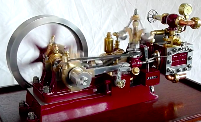

Please Consider Making a Donation