Stoking the steam, one engine at a time…
Model boat club
Stuart Turner logo
  • © 2018 Steve Allen Contact Me 0
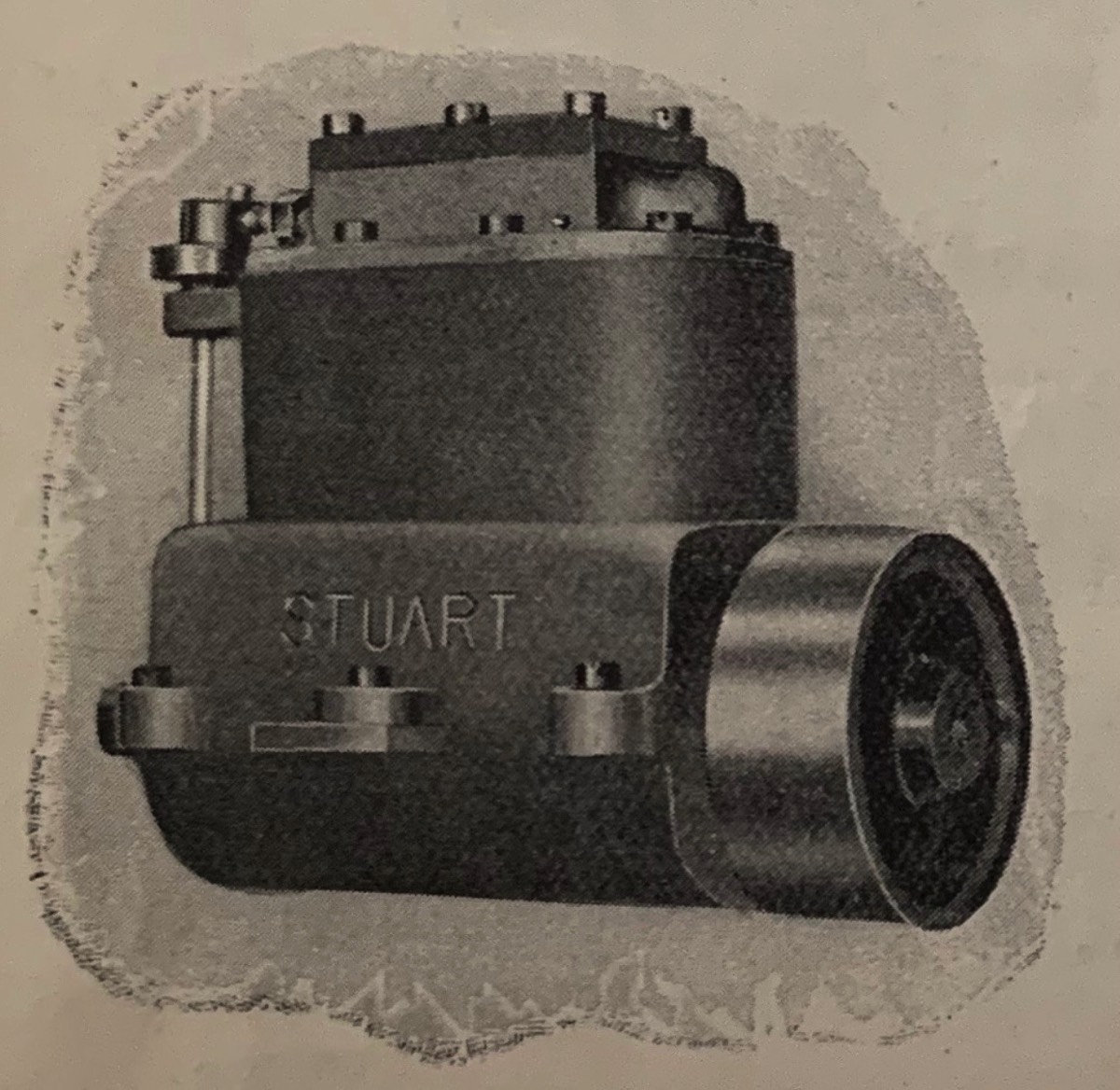
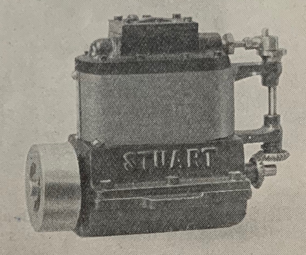
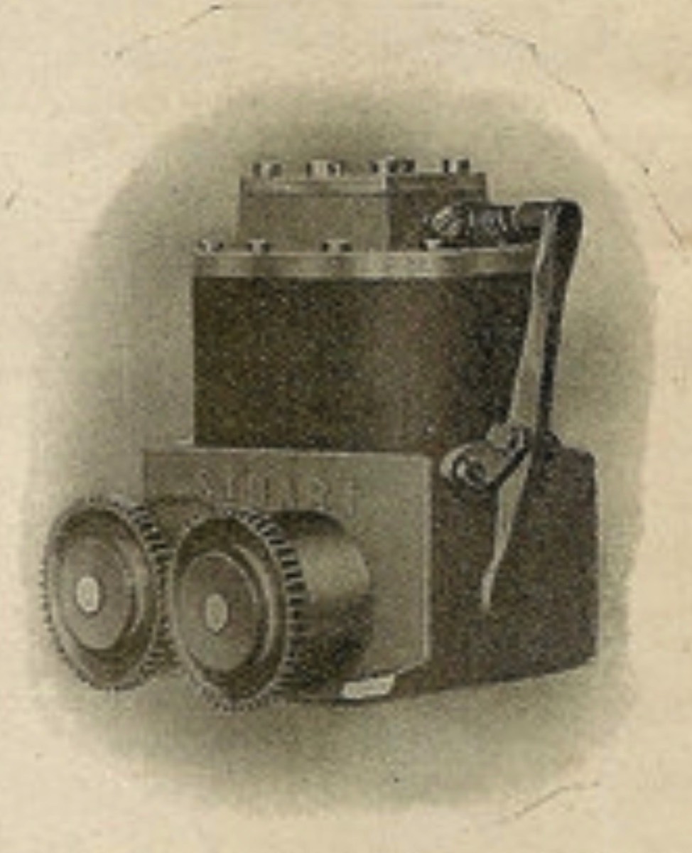
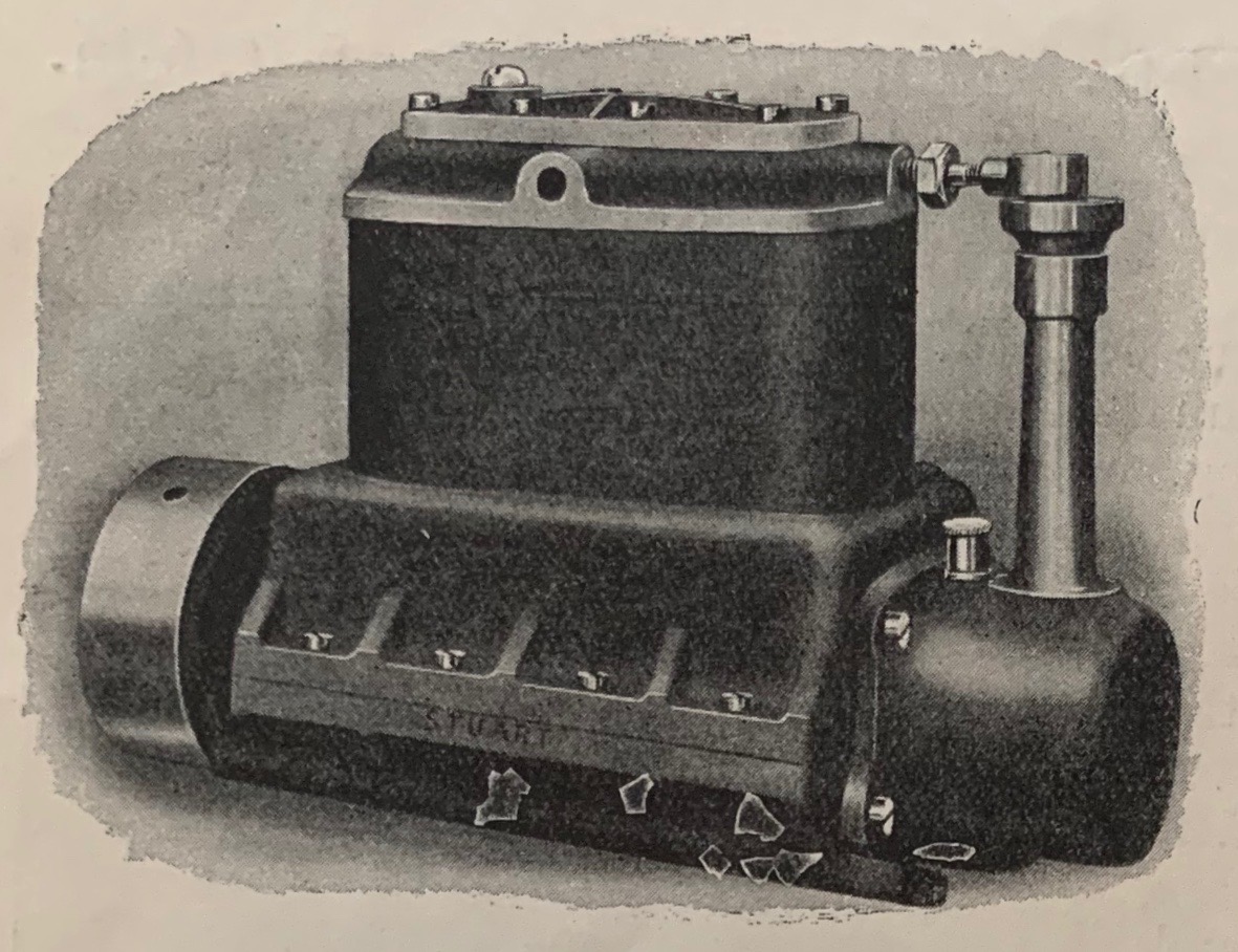
Marine TwinsHigh speed steam

Type: Vertical, single cylinder, double acting, slide valve.
Bore 2 in
Stroke: 2 in
Height: 13 in
Availability 1906-Today.
Design: Standard & Rod.
RPM: 1500
BHP: 1/4 @ 1000 RPM @ 50 PSI


HiGH SPEED ENCLOSED
SINGLE ACTING ENGINES
With Balanced Pistons.

Stacks Image 155

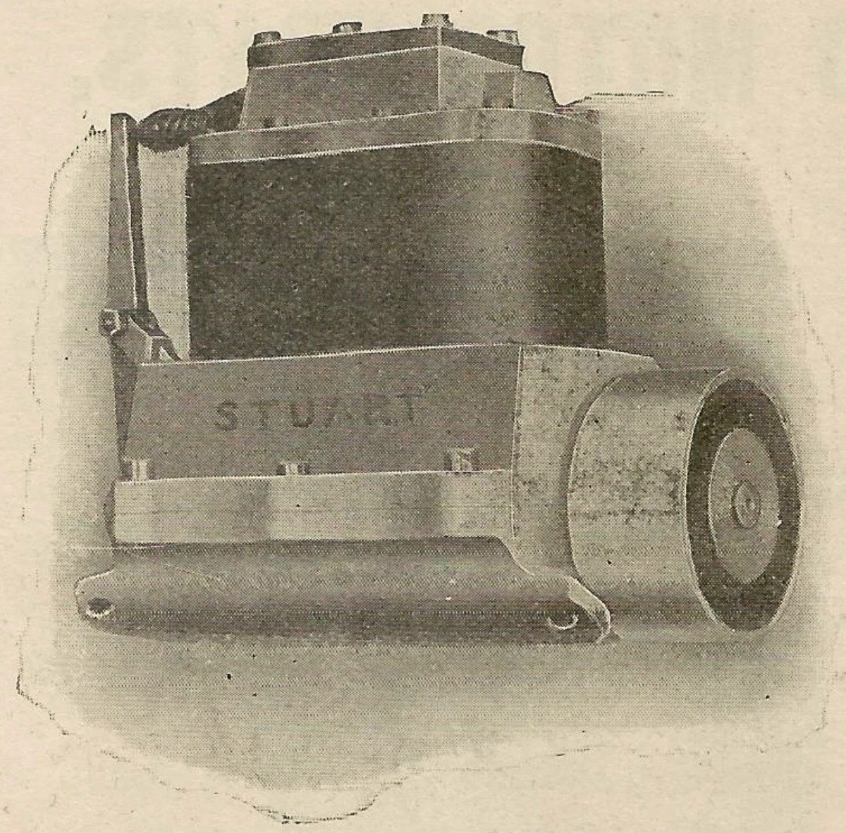
Up-to-date designs, specially suitable for
FAST MODEL TORPEDO BOAT DESTROYERS

That the Single-Acting Steam Engine has many points of superiority where extremely high speeds are required, is well-known, and among modern examples may be mentioned the "Willams" "Westinghouse" and "Peache" Single action high speed engines. This fact coupled with the desire to provide a suitable engine for speed boats which should be light (for the power developed), have a small number of working parts, be compact, and take up very little bed room, has led us to design and produce engines illustrated herewith.
All the engines have twin cylinders with a single steam chest containing one Slide Valve. Not. 1 and 1a have two cylinders placed longitudinally. This provides a perfectly balanced engine for a single screw or, in the case of a large twin screw model, one engine on each screw shaft may be used.
Engine No.2 has cylinders arranged transversely, for twin screws, the fly-wheels being fitted with gears which ensure regular working and equal power distribution.
In Engines No. 1 and 2, the cylinders, pistons and crank chambers are made of good cast iron, thus ensuring almost ever-lasting wear. The crank shafts are steel, valves and valve gear are gunmetal. To obtain high speed the valves are operated by cams (not ordinary eccentrics) the friction is reduced to a minimum by a novel arrangement of a steel ball held up to the cam lever by a spring.
The No.1 and 2 Engines are fitted with cam gear and are suitable for low pressures.
Engine No.3 is of a similar design to No. 1a but is fitted with bevel driven valve gear (as No.1a). Cylinders, pistons and valves are of cast iron. It has solid steel crankshaft and cut steel gears.
Stacks Image 161

M.T.B. 1a (featherweight)

Stacks Image 165
Stacks Image 149

M.T.B. 2 Twin Screw Engine for 4ft. 6in. Boat.

Stacks Image 157


Design

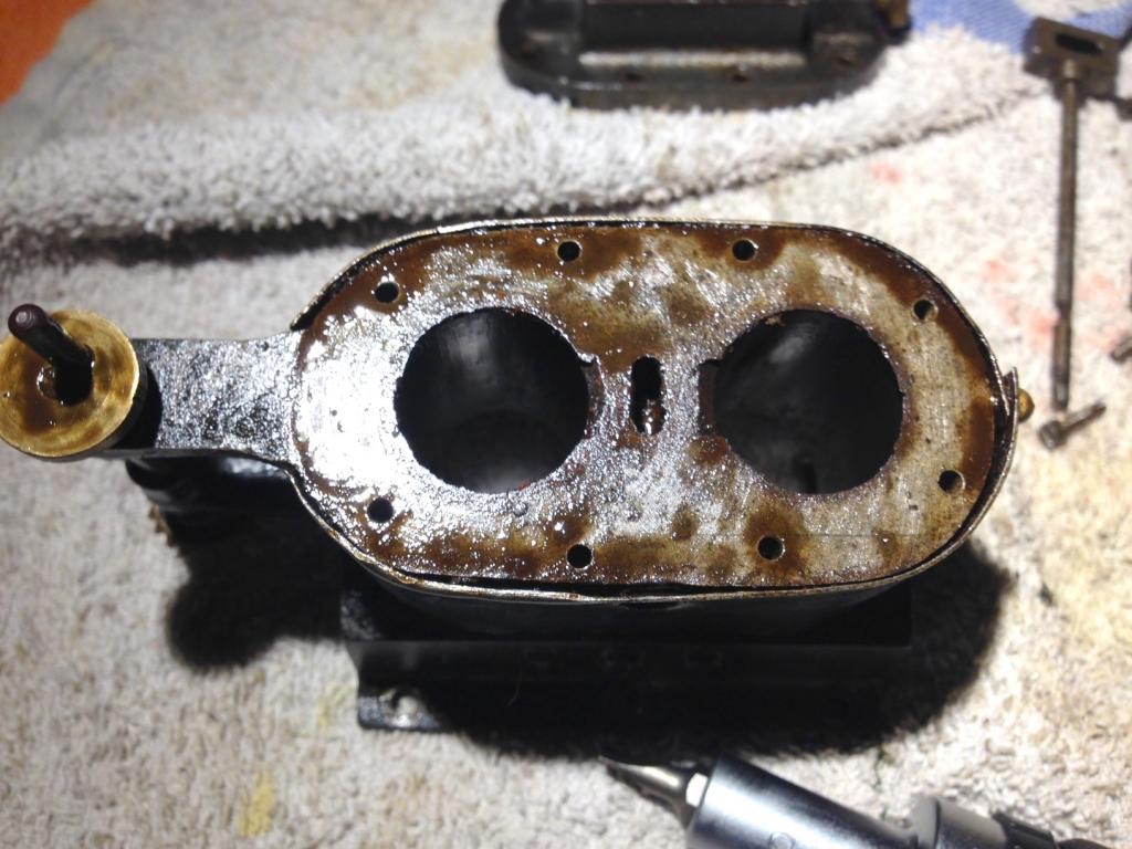
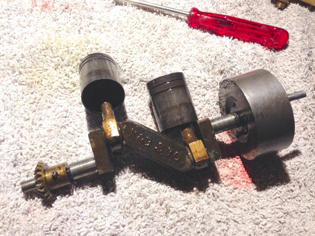
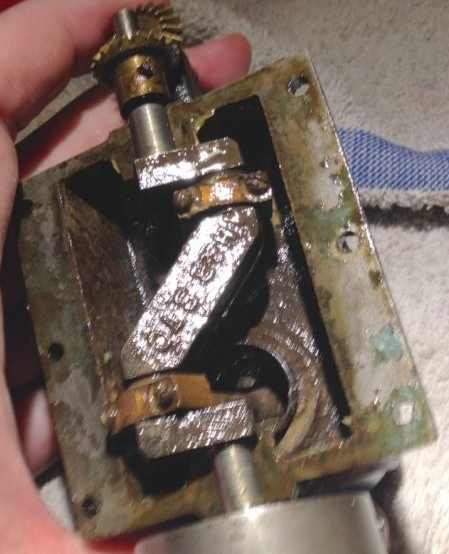
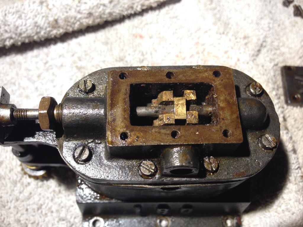
With increasing interest in model high speed steam boats and competition from other manufacturers, Stuart decided to add to the Stuart BB, a range of twin cylinder engines. Reqirements for a high speed boat differ greatly from normal steam boats. They require Light weight, Low height, small bed space, high speed running, low vibration, simple design. To achieve all these requirements an number of features conveniently combine to create avery nice model boat engine. The engines are all variations on the same theme but with slightly different capabilities. I will deal with individual characteristics on the seperate engine pages but here I will concentrate on the overall design features. To reduce the height and weight of the engines Stuart removed the piston rod and gland and mounted the small end of the connecting rod directly to a gudgeon pin mounted in the top of hollowed pistons, not unlike the pistons in an Internal Combustion Engine. The pistones being hollow alows a long piston with a small sealing surface with eirther sealing grooves or piston rings. This reduces the height considerably. Having the pistons directly above the crankshaft and mounting it in a wet sump oil bath allows oil splashed up from the crankshaft to lubricate the bottom of the cylinders which is dragged up the bore by the pistons. It also lubricates the gudgeon pin. Valving a single cylinder in double acting mode ( piston pushed up and down by steam in two strokes.) would be very complex so by mounting two cylinders side by side in single acting mode (piston only pushed down by steam) allows for very simple valving. The slide valve is mounted in a top casting allows for very simple machining. Control of the valve varied with the different engines being a cam, eccentric or bevel gears. The twin cylinder arrangement also reduced vibrations considerable as whilst one goes up the other goes down, balancing each other out. Construction is essentially the same with a top casting containing the valve, a middle casting with the twin cylinders cast in with a light weight structure and a bottom casting consisting of an oil sump and mounting brackets. The crankshaft bearings are cast into the bottom and middle castings on the joint line. The oil level was filled up to a point bellow this split line to reduce leakage, the crankshaft splashing into the oil easily moved it arround the inside of the engine. The bearing surfaces must have proved troublesome as in all later engines seperate bearings were mounted onto the castings. Steel clading was mounted over the cylinders to reduce condensation and maintain heat once the engine has started up. The exposed valve gearing was a bit of a problem being difficult to maintain lubrication and easily damaged. Later designs enclosed the gears.


Stacks Image 175
M.T.B. 1a Featherweight. Castings


The photo above shows a set of castings for the M.T.B. 1A also known as the featherweight. This is because it is the only one of the engines to be constructed from an aluminium alloy. The top left cast is the middle casting that contains the cylinders. On the right hand side is the bracket that mounts the external valve gearing. The two holes are obviously not the cylinder bores, on this engine they used triple hard drawn brass tubes press fit inserted into the casting. To the right is the bottom casting showing the mounting tabs and the extra thickness at the sides that will be machined into the crankshaft bearings. Next down on the right is the upper casting that contains the valve. Ports cut into the bottom middle of the casting allow steam into the cylinders and out again. Next down is the cast crankshaft designed to be lightweight and requiring minimal machining. The marine style flywheel is hollowed out to reduce weight whilst maintaining mass at the edge.The middle appears to have casting sand still in the voids. In the middle can be seen three blobs the two opposite are for mounting drive pins to connect the engine to the prop shaft. The third is to allow a fixing grub screw to be drilled in from the outside.
The two castings at the bottom are the connecting rods for the pistons. The extra bit on the left one is the scotch crank used to drive the valve.


Stacks Image 215
M.T.B. 1b. Showing top of the cylinder casting, the central exhaust port and beveled inner edge of cylinder bores for the steam inlet.


Stacks Image 210
M.T.B. 1b. The pistons showing clearly the hollow nature and connecting rods pivoting at the top.


Stacks Image 205
M.T.B. 1b The crankshaft bearings are clearly machined into the cylinder block casting. The wet sump nature of the oiling with oil level just below crankshaft, splashing of crank ensures ample lubrication.


Stacks Image 220
M.T.B. 1b valve setup feeding and exhausting two cylinders in the same way as most dual actions valves run steam to both sides of a single piston.


Video of Stuart 180 AKA M.T.B. 1b

180video

Please Consider Making a Donation